
当电气设备在使用时,由于导体电阻的热效应,电气部件及线路会发热;由于开关、继电器等电气元件正常工作时引起的电路通断,会产生电气火花或电弧;由于电气部件之间的绝缘或间距不够,不同电势的导电部件之间会发生短路、击穿等故障而发热、产生电气火花或电弧,这些在普通环境中可能仅仅引起设备故障、线路故障等,但如果在爆炸性环境中,将可能点燃爆炸性环境中爆炸性物质而爆炸。因此,有必要采取措施,防止电气设备引起爆炸事故。
直接的措施是,不考虑设备的工作原理、功率大小,将电气设备都安装在一个足够坚固的外壳内部,即使电气设备引起其周围的爆炸性物质的爆炸,由于被外壳包裹,爆炸产生的高温、高压不会扩散到整个环境中,从而不会导致更加严重的后果。
因此,这个外壳首先应当具有足够的强度,以承受内部爆炸产生的压力,在GB/T 3836.2“爆炸性环境 由隔爆外壳“d”的保护的设备”中,该隔爆外壳需要至少承受1.5倍内部爆炸压力。
另外,设备在爆炸性环境中使用时,外壳本身也不应当成为点燃源。长期的运行时,设备外部的表面不应有足以引起点燃的高温。设备内部的高温即使引起点燃,也无法传播到外部,无需考虑其点燃风险,但应当防止断电后马上开盖,高温表面的温度还没有下降到低点燃温度以下,因此,有必要在外壳外部施加警告标志,需要断电足够时间后方可打开盖板。
当外壳采用金属材料制造时,如果受到外部的敲击、摩擦,可能会产生机械火花,引起点燃。铝、镁、钛锆等轻金属被生锈的铁碰撞后,极易产生高温的机械火花,因此,应当严格控制金属外壳材料中的轻金属成分的比例。需要注意的是,虽然大部分情况下,铜及铜合金都是不发火,被其它金属碰撞后不会产生高温机械火花,经常被用作防爆工具,但是铜可以和乙炔形成乙炔化物,受到摩擦、碰撞后,乙炔化物会剧烈燃烧,因此,如果设备预计用于有乙炔的环境,外壳材料应控制铜的含量不超过65%。
外壳还应当具有足够的稳定性,不应在日常使用中发生腐蚀,活性高的锌及锌含量超过80%的合金就不适合制造防爆设备的外壳。
当外壳采用除玻璃、陶瓷以外非金属材料制作时,除了需要考虑其在长期工作中,因承受高温、低温而引起的性能下降外,对用于煤矿井下的灯具透明件、非矿用场所的外壳,还需要考虑其因暴露在紫外线中而引起的性能下降。另外,非金属受到摩擦后会积聚静电,当静电在足够高的电势放电时,将点燃环境中的可燃性物质。因此,需要避免产生静电或防止静电积聚,可以选择防静电材料或尽快将静电释放的措施来降低静电点燃的风险。
电气设备在制造、使用时,不可避免地需要打开外壳进行安装、调试、检修等工作,不可能将外壳焊接成一个完全封闭的整体,在外壳上就不可避免地形成了两个不同部件接合的结构,在接合的位置上存在着间隙,为了防止设备内部的爆炸火焰从接合部位的间隙传播到周围环境中,需要对接合的结构进行特殊的设计。根据已有的研究,火焰沿着狭窄的缝隙传播时,间隙越小,越能降低传播到外部的能量,当间隙足够小,内部的火焰将无法通过接合部位引起外部环境的点燃。另外,火焰通道的长度越大,对火焰能量的降低效果越好。在防爆标准中,这样的火焰通道被称为隔爆接合面,根据大量的试验,得出了不同防爆等级的隔爆接合面宽度及其相应间隙的安全值,当接合面宽度大于这些小值、间隙小于大值,隔爆外壳是可以有效地防止内部火焰传播到设备周围环境中的。
隔爆接合面的型式主要有平面型、圆筒型、止口型、螺纹型、粘结型。无论是哪种型式,都是内部爆炸火焰向外传播的通道,在设计时,应当考虑不利条件下的情况。
由于紧固方式多种多样,平面接合面的宽度及距离的位置也有多种变化,常见的主要有外固定式、内固定式、连通腔体固定。

图1 螺栓从外侧紧固
首先,我们来看图1所示的常见的平盖板通过螺栓从外侧紧固在法兰上的结构。在这种紧固的方式中,螺孔可能是通孔或者不通孔,壳体可能在法兰的外侧,也可能在法兰的内侧,虽然螺孔的形状和壳体位置不相同,但是隔爆参数都是一样的,很显然,在这种情况下,火焰传播的通道有两个:第一个的沿着整个平面接合面的间隙向外传播;另一个是沿着平面接合面传播到紧固螺栓处,从螺栓孔处向外传播。因此,这种结构需要控制的隔爆面参数包括:总的有效隔爆面接合宽度,孔内侧到法兰边缘的距离。当螺孔是不通孔时,还应注意GB/T 3836.2-2021中对螺栓头部裕量的要求,防止螺栓在不带垫圈拧入时无法拧紧。
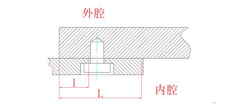
图2 螺栓从内侧固定
有些情况下,需要从内侧固定盖板,例如在图2所示的有些变频器的散热器结构中,由于散热器热管外面套的散热翅片较大,无法从外侧拧螺栓,这时就需要先从内侧将散热器基板固定在过渡法兰上,再将过渡法兰装配到隔爆壳体上。这种结构里,沿着整个平面的传播通道依然存在,但是从基板和法兰外侧边缘向螺栓处传播时,通道两侧都是外壳内部,不会发生传爆,因此这一通道不需要按照隔爆接合面进行设计,只要符合GB/T 3836.2-2021中隔爆外壳壁的剩余厚度的要求;但是如果火焰从螺栓孔处沿着平面向过渡法兰的内侧传播,可以到达壳体外部,会引起外部的爆炸,因此这一通道就需要符合隔爆接合面要求。通过简单的分析,这种结构需要控制隔爆面参数包括:总的有效隔爆面接合宽度,孔边缘向内到过渡法兰边缘的距离。
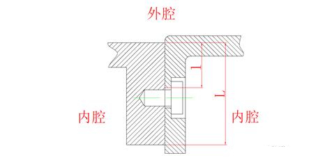
图3 螺栓连接两段连通的壳体
在另外一些情况下,需要将如图3所示两段壳体用螺栓从内侧固定在一起,但是两段壳体没有被隔开,例如多回路组合开关,外壳很长,为了加工方便,制造单位往往将其设计成多段,然后装配成一个完整的外壳。在这种结构中,火焰传播的路径与上面的情况有些区别,火焰从螺栓孔沿着平面往法兰内侧传播时,内侧仍然是隔爆外壳内部,但是向法兰外侧传播时会达到壳体外部,这一通道就需要符合隔爆接合面要求以保证火焰不会传播到外部引起周围环境的爆炸。因此,这种结构需要控制的隔爆面参数是:总的有效隔爆面接合宽度,孔外侧向外到法兰边缘的距离。
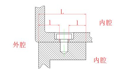
图4 螺栓连接两段被隔开的壳体
当这种结构产生一些变化时,如果需要用法兰将如图4所示两个被隔开的壳体连接时,就需要考虑不同的火焰通道了,例如隔爆型电机的接线盒与机座处的隔爆接合面,在这种结构里,火焰能够从法兰内侧或者从螺栓孔处向法兰外侧边缘沿着接合面传播,可能引起隔爆外壳外部环境的爆炸,同时,当火焰从法兰内侧传播到螺栓孔处,就会引起另外一个腔体的爆炸,因此在这种情况下,整个结合面宽度、螺栓孔边缘到法兰外侧边缘的距离、螺栓孔边缘到法兰内侧边缘的距离均需要符合隔爆接合面的要求。
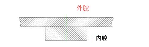
图5 法兰中间无螺栓紧固
有时候,法兰会比较狭长,制造企业为了对其进行加固,会在中间加一道加强法兰,如图5所示,如果这段法兰上没有紧固螺栓,也没有将腔体隔成两部分,那么这里就不需按隔爆接合面进行设计。
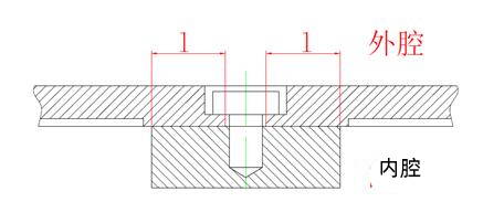
图6 同一腔体的法兰中间有螺栓紧固
但是有些情况下,由于接合面比较大,仅靠周边的固定无法保证爆炸时盖板强度,因此中间法兰上会有紧固螺栓,如图6所示,这时就需要考虑火焰通道了,由于法兰两侧是同一个腔体,所以整个平面接合面不需要满足隔爆接合面宽度,但是如果火焰从法兰边缘沿着接合面传播到紧固螺栓孔边缘时,或从螺栓孔传播到壳体外部,因此这段接合面需要符合隔爆接合面的距离。
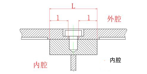
图7 不同腔体之间的法兰用螺栓紧固
另外一些情况下,两个相邻的腔体共用一块盖板,如图7所示,例如在大功率的输送机电机上,电机腔和接线腔在上方共用一块盖板。这种结构里,除了法兰边缘到螺栓孔的距离需要符合隔爆接合面的距离外,火焰如果沿着整个接合面传播,也会从一个腔传播到另外一个腔,从而引起该腔的爆炸,因此法兰的有效接合宽度需要满足隔爆接合面的宽度要求。
为了显示电气设备的信息或者将光源的光传播到外部,在外壳上还需要安装透明件,除非昂贵的聚碳酸酯等材料可以进行钻孔或机加工以满足隔爆面的固定及尺寸精度要求,大量使用的钢化玻璃是无法保证尺寸精度的,只能采取其它手段满足隔爆接合面的要求。目前矿用设备大多采用衬垫安装的方式,便于更换,但由于接合面间隙较大,不能保证通过II类设备的内部点燃的不传爆试验。II类设备的透明件基本采用粘结接合面的方式,这种接合面中的粘结剂一般只保证密封效果,透明件需要靠机械结构固定。目前也有特殊的熔融接合面,将玻璃融化后浇铸在外壳或框架内,玻璃和金属部件之间几乎没有间隙,但这种工艺成本高,一般不采用。
电气设备通常都有和其它设备的线路连接,以实现供电、控制、通讯等功能,防爆电气设备是采用电缆以实现这些功能。然而由于电缆是采用有弹性的橡胶制成,无法像金属或塑料那样加工成外尺寸固定的圆柱形,并且电缆在安装后的位置也应当有足够的稳定性,防止在使用过程中被拉扯而导致线路故障。基于电缆材料和结构的特点,一般都采用带孔的圆柱形密封圈套在电缆外部的方式,将其与金属垫圈一起安装到联通节内,用各种方式的压紧装置轴向压缩密封圈,使其径向膨胀,由于密封圈外侧联通节的原因,密封圈只能向内侧膨胀,从而与电缆紧密结合,达到夹紧电缆的作用,这个结构被称为电缆引入装置。对于隔爆外壳上使用的引入装置,除了需要夹紧电缆,还应当防止内部的火焰通过密封圈与电缆、密封圈与联通节之间的间隙传播到环境中,因此,还应额外进行密封试验,确认其防止火焰传播的能力。对IIC类设备,或者电缆过短的情况,还应考虑火焰从电缆内部传播的风险,一般建议隔爆外壳外部的电缆长度不宜小于1米。
隔爆外壳的小结
采用隔爆外壳保护的方式不需要对电气部件进行改造或降低其性能使用,对电气设备的类型也没有限制,应用方便,是使用多的防爆型式。但是由于外壳需要承受内部爆炸压力,结构笨重,也会增加制造成本。

.jpg)
.jpg)
.jpg)
.jpg)
.jpg)