range
1、 It specifies the inspection procedures, data review, prototype testing, and testing of intrinsically safe electrical equipment for explosive environments. This testing implementation rule is a supplement to the requirements of GB3836.4, GB 3836.18-2010, etc.
2、 The inspection of intrinsically safe electrical equipment suitable for explosive environments can also be followed for products such as mine lamps.
Inspection basis
GB3836.1-2010 Explosive Atmosphere Equipment Part 1 General Requirements
GB3836.4-2010 Explosive atmospheres Part 4: Equipment protected by intrinsic safety type "i"
GB 3836.18-2010 Explosive Atmospheres Part 18: Intrinsic Safety Systems
GB 3836.19-2010 Explosive atmospheres Part 19: Concepts of intrinsic safety for fieldbuses
GB4208-2008 Housing Protection Level (IP Code)
GB 12476.4-2010 Electrical Equipment for Combustible Dust Environments Part 4: Intrinsic Safety "iD"
Inspection procedure
1. The inspected unit shall prepare technical materials related to the explosion-proof performance of the applied product in accordance with Appendix D of GB3836.1-2010 (a power of attorney signed by the enterprise legal representative shall be required for enterprise authorization, and a safety technical review task book shall be required for safety authorization); Registration with the Business Office of the Transportation Center;
2. The business department will submit the received technical data and acceptance form to the explosion-proof room, and issue a technical review task book at the same time;
3. After receiving the information, the explosion-proof room is registered by a dedicated person and hung on the internal network. All authorized personnel can download it from the internet; After the main reviewer receives the task, they fill in the relevant information and return it to the data receiver, who will summarize it. The technical data registration form should reflect all time points for easy task monitoring.
4. Task distribution: Regular tasks are registered and completed by the data receiver, and then handed over to the director of the technical review room to arrange for the main reviewer. Import or other special tasks shall be arranged by the director or deputy director of the explosion-proof room. Time does not exceed 24 hours.
5. Review method: The review adopts a two person review method that combines the main review and the second review.
6. The time limit for review is divided into three categories: simple, general, and complex. Simple data generally does not exceed 0.5 working days, general data review takes 1 working day, and complex data takes 2 to 3 working days. The specific time limit shall be proposed by the task distributor.
7. After receiving the technical materials, the chief reviewer shall make an audit plan in accordance with the requirements of the reviewing commissioning unit, and conduct the audit in accordance with standards such as GB3836. The audit content includes product standards, drawings, user manuals, control details, calculation sheets, and
Technical information related to explosion-proof review, such as material inspection reports, should be recorded in the review. After the initial review is completed, the review shall be submitted for review. The verification personnel shall fill out the verification record form. After the review personnel have no doubts, the main auditor shall promptly notify the inspected unit of the review opinions and record the contact information, contact person, and main matters in the record card. Communication with clients should be prepared in advance, and all issues should be reported at once with written records.
8. After the modification of technical data, the reviewer should promptly arrange for re examination and keep records after receiving the modified data from the inspected party. For issues that still do not meet the requirements after modification, timely feedback should be provided to the inspected party and the processing time and nature of the problem should be recorded in the memo card. These issues are either not fully modified or generated after modification. The modification process may be repeated multiple times, but the reviewer must clearly record the processing timeline and main matters on the scorecard; Materials that have been modified twice or more but still fail should be reported to the inspection room.
9. After the review of paper materials is qualified, the drawings and materials are confirmed and signed by the delivery reviewer, and the drawings and materials are stamped. The stamping of the drawings is completed by the reviewer, and only the materials involved in the review process are stamped. Unrelated drawings do not need to be stamped;
10. After stamping, one copy of the documents shall be submitted to the inspected unit, and the other copy shall be temporarily stored by the reviewer. After the test is qualified and certified, it shall be archived and kept together with the inspection report and explosion-proof certificate.
11. For the technical data review of products entrusted with sample submission for the first application, modifications can be proposed in conjunction with product inspection. However, all technical review work should be completed before issuing the report and issuing the certificate of conformity. The review records should be filled out completely, signed completely, and the drawings have been stamped and delivered to the inspected party.
12. Prototype inspection and testing shall be carried out in accordance with relevant regulations of the center
Technical review
Technical review includes standard review, drawing review, user manual review, and review of explosion-proof related materials provided by the enterprise. Equipment that only uses semiconductors and controllable semiconductors for current limiting protection cannot be classified as "ia" level.
Device Description
Technical review should clarify the explosion-proof type and working principle of the equipment; Please describe the power supply method of the equipment, including wireless, infrared, laser, ultrasonic, etc; If it is a product change, list the changes and how the changes will affect the explosion-proof performance.
Final assembly drawing
Complies with the provisions of GB4457-4460 Mechanical Drawing. The overall drawing should reflect the basic structural characteristics of the product, with a detailed list of parts, external dimensions, markings, and identification; The technical requirements should include the following content: reference standards, requirements for shell protection level; Requirements for surface insulation resistance (if any); Working voltage, working current; The electrical clearance and creepage distance of intrinsically safe terminals, as well as the spacing between intrinsically safe and non intrinsically safe terminals.
Special attention should be paid to:
a) The metal material content of the metal shell and its metal components meets the requirements of Article 8.1 of GB3836-1-2010 (with particular attention to the requirements for lightweight alloys; Class I portable instruments, lamps, and electric drills can use lightweight alloys that meet the friction spark test method specified in GB/T13813-2008 and meet the requirements of Class II EPL Ga and EPLGb); Description of non-metallic materials: Surface area size and surface insulation resistance<1G Ω.
b) If there are series products, the differences between different models of products and their impact on explosion-proof performance should be explained in detail, and relevant drawings should be attached.
c) If other explosion-proof types are included in the composite product, corresponding drawings should be attached. If there are certified explosion-proof components in the system, the model name/explosion-proof mark and explosion-proof certificate number should be marked, and a copy of the explosion-proof certificate should be attached.
Mechanical structure diagram
The product should have shell drawings, sealing strip drawings, and wiring terminal diagrams;

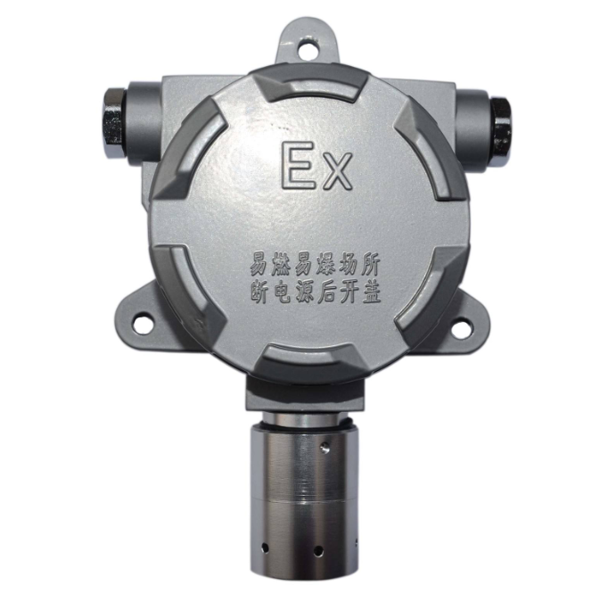

POS machine gas and dust detector explosion-proof mobile phone
Electrical schematic diagram
Review the components or circuits in the electrical schematic that affect the intrinsic safety performance, and provide a specific description according to the provisions of GB3836.4. Confirm the intrinsic safety parameters (voltage, current, inductance, and capacitance), record and analyze them, and evaluate them.
If there are both intrinsically safe and non intrinsically safe circuits in the circuit, the intrinsically safe circuits need to be marked with dashed boxes.
If the circuit or device is sealed to meet the requirements, the sealed part should be marked with a dashed box and the sealing process document should be provided.
a) Reliable components:
Transformer, current limiting resistor;
——The structure of the transformer should comply with the requirements of Article 8.1.2 of GB3836.4-2010; If it is a power transformer, its primary should be protected by a fuse; The structure diagram of the transformer should be provided (special attention should be paid to marking the thickness of the shielding layer, winding spacing, thickness of the solid insulation layer, and voltage resistance requirements between each winding)
——Current limiting resistors can only be thin film, wound, or printed resistors;
b) The rated value of components related to intrinsic safety shall meet the requirements of Article 7.1 of GB3836.4;
——Current limiting resistor;
——DC/DC power chip;
——Sampling and comparison circuits in semiconductor current limiting circuits, MOSFETs, transistors;
——Zener diodes and thyristors in semiconductor voltage limiting circuits;
——The switch chip in the switching power supply circuit.
c) Evaluation of pure resistance circuits: Calculate whether the current at the corresponding voltage in the circuit meets the requirements of the curve or table in Appendix GB3836.4.
d) Evaluation of capacitance: Calculate the maximum capacitance of each voltage level under technical and non-technical fault conditions at ia and ib, and evaluate according to the curve or table in the appendix of GB3836.4. Apply a safety factor of 1.5 during the evaluation. When the capacitor is connected in series with a resistor according to Appendix F of GB3836.4 to increase the safety factor, the resistor and capacitor should be encapsulated as a whole;
e) Evaluation of inductance: The maximum (equivalent) inductance value is calculated by applying technical and non-technical faults based on the corresponding and explosion-proof level (ia, ib) of electrical induction, and the current on the inductance is calculated
Calculate the energy using the formula and evaluate it using the energy given on the curve in the appendix of GB3836.4; When evaluating, a safety factor of 1.5 is applied. When the inductor is connected in parallel with the diode, the inductor must be encapsulated as a whole with the diode; Special attention should be paid to the applicability of sealing for rotating motors to prevent ignition of shaft end clearances.
f) Isolation device:
——Transformer;
——Optocoupler;
——Relay;
——Capacitors (IA protection level requires 3 capacitors to be connected in series, IB protection level requires 2 capacitors to be connected in series);
Note: In addition to meeting the requirements for voltage resistance, the spacing of optocouplers, relays, and capacitors should also meet the requirements of Table 5 of GB3836.4.
Printed board diagram
Confirm the voltage, current, inductance, and capacitance involved in the installation diagram of printed circuit boards and components combined with the component list.
The printed layout should record the following information
——The printed circuit board diagram should be consistent with the actual product.
——The technical requirements should include dimensions, printed board thickness, conductive film thickness, printed line width, and board line spacing;
battery
The review of batteries and battery packs should record the following information:
a) Battery and battery pack structure type: sealed or shell sealed;
b) The maximum open circuit voltage of the battery: When complying with the provisions of Table 10 and Table 11 of GB3836.1, the voltage in the table shall be taken. Batteries not listed in Tables 10 and 11 shall be treated as non tight components, and the maximum open circuit voltage shall be determined through testing according to 10.5. The nominal voltage shall be taken as specified by the battery manufacturer.
c) Internal resistance of batteries and battery packs: The internal resistance of batteries and battery packs should be determined according to 10.5.3. If a current limiting resistor is used to limit the possible current generated by the battery pack, its rated value should meet the requirements of 7.1.
Note 2: When it is necessary to use current limiting devices to protect the output safety of the battery pack, do not require current limiting devices as integral components of the battery pack.
d) Current limiting devices:
——When the battery pack is intended for use and replacement in explosive environments: the battery pack should form a replaceable component with current limiting devices. The unit components should be sealed or sealed, and only intrinsically safe output terminals and appropriately protected charging intrinsically safe terminals (if provided) can be exposed.
——The battery pack should not be replaced in explosive environments: The battery or battery pack can be installed in a chamber with special fasteners specified in GB3836.1 according to the requirements for the intended use and replacement of the battery pack in explosive environments.
e) Connection method: The layout of the battery, battery pack bracket, or device connection method should ensure that the installation and replacement of the battery or battery pack will not reduce the intrinsic safety performance of the device.
f) Handheld or portable electrical equipment: For complete handheld or portable electrical equipment, it should withstand the drop test specified in GB3836.1 26.4.3. If there is no detachment or separation between the battery pack and the equipment that causes the intrinsic safety performance of the equipment or battery to fail, the equipment structure is considered qualified.
g) Warning signs: The equipment should have the warning signs specified in GB3836.1 clause 29.11.
h) External charging contacts: For batteries or battery pack components with external charging contacts, measures should be taken to prevent short circuits or to prevent individual batteries and battery packs from releasing enough energy to ignite the contacts when any pair of contacts may accidentally short circuit. Blocking diodes or series reliable resistors should be used.
Note: The highest voltage Um that may be applied to these charging contact connectors should be marked on the device and can be controlled
Explanation in the figure.
i) Battery structure
The spark ignition ability and surface temperature of batteries and battery packs should be tested and evaluated in accordance with the provisions of 10.4.3.
The structure of batteries and battery packs should be sealed (airtight) batteries and battery packs, valve controlled sealed batteries or battery packs, with pressure release devices, and sealed in the same way as the previous item.
These batteries or battery packs should not require electrolyte replenishment throughout their entire lifespan and have metal or plastic sealed enclosures that meet the following requirements; No need to verify that the battery or battery pack meets the manufacturer's technical requirements.
Unrestricted components according to regulations
It is stipulated that ten unused component samples should be taken from any source or several sources for non tight components, and their relevant parameters should be measured. Usually, the test should be conducted at the specified maximum ambient temperature (e.g. 40 ℃), or based on the highest ambient temperature. But if necessary, temperature sensitive components (such as nickel cadmium batteries/battery packs) should be tested under low temperature conditions to obtain their most unfavorable conditions.
Different parameters can be taken from different samples, and the representative parameters of the component should be the most unfavorable values obtained from testing 10 samples.
Unrestricted components refer to components without standards or with incomplete parameters despite having their own standards; These parameters are essential for evaluating the intrinsic safety performance of the equipment.
Component List
The component list should be verified to be consistent with the electrical schematic, and the tag number, drawing number, rated value, production unit, etc. of the components should be clearly defined.
Nameplate
The drawings should clearly specify the material and pasting method of the nameplate; The content of the nameplate should include: explosion-proof mark, working voltage, working current, intrinsic safety parameters, safety label number, explosion-proof certificate number, and production date.
Enterprise standards
The review of enterprise standards should pay attention to the following points
——Reference standards: GB3836, GB4208-2008, etc
——The explosion-proof type and explosion-proof mark of the product
——Product usage environment
——Product testing requirements and methods
a) Intrinsic safety parameter testing:
b) Shell protection level test
c) Measurement of electrical clearances and creepage distances
d) Spark ignition test
e) Dielectric strength test
f) Maximum surface temperature test
g) Insulation resistance test on the surface of the casing
h) Battery leakage test
i) Explosion proof drop test
j) Isolation device withstand voltage test
k) Routine and type tests of transformers;
User manual
The review of the user manual should pay attention to the following points
——The cover should have a reference standard GB 3836
——Product explosion-proof type and explosion-proof marking
——Product usage environment
——Product intrinsic safety parameters
——Safety warning language, warning language
Service hotline: 18924609560 (same WeChat account)
.jpg)
.jpg)
.jpg)
.jpg)
.jpg)